Looking for hardware solutions that meet European / American standards?
Use this guided inquiry modal to move from a generic quote form to a clearer technical conversation. Buyers can choose whether they need pricing, CAD / 3D files, or OEM / ODM support before sharing contact details.
Compatibility-first design across door / window systems
Repeatable production with clear inspection checkpoints
Documentation and change control for long-running programs
Responsive engineering support for fit and field feedback
Yet a complete hardware BOM for an aluminum door or window system must connect mechanical interfaces, operating loads, profile dimensions, corrosion exposure, accessibility requirements, replacement logic, packaging quantities, test evidence, and supplier revisions in one controlled document.
Why do so many companies still send suppliers a spreadsheet with three columns?
I will be blunt: most hardware BOMs are not BOMs. They are purchasing lists wearing engineering clothes.
“Black handle, four hinges, one lock” may be enough to request a rough price. It is nowhere near enough to manufacture, inspect, install, service, and reorder an aluminum door or window system without unpleasant surprises.
A proper door and window bill of materials must answer five questions:
What exact part is required?
Where does it fit?
What performance must it deliver?
How will conformity be verified?
What happens when the part or drawing changes?
Miss any one of those, and the risk does not disappear. It merely moves downstream, where it becomes more expensive.
A Hardware BOM Is a Control Document, Not a Shopping List
A hardware BOM is the controlled technical record of every purchased, manufactured, and packaged component required to build one approved door or window configuration.
That includes obvious hardware such as handles, hinges, lockcases, gearboxes, rollers, keeps, and fasteners. It also includes the parts that buyers routinely forget:
Spindles and connecting bars
Corner drives and extension rods
Packers and shims
Anti-lift devices
Restrictors and opening-control devices
Bushings, washers, clips, and retaining rings
Striker plates and adjustment screws
Gaskets beneath escutcheons or hardware bases
Thread-locking compounds
Lubrication requirements
Identification labels
Installation templates
Replacement-part references
Inner-box and master-carton quantities
Small parts cause large failures.
A missing €0.08 retaining clip can stop a €600 door assembly from operating. An unrecorded 2 mm spindle change can generate an entire container of handles that look correct but never engage the gearbox. A substituted zinc-plated screw can start corrosion beside an otherwise well-finished aluminum profile.
That is why I begin with the system, not the catalog.
Freeze the System Architecture Before Entering Part Numbers
The worst time to discover the opening logic is after the supplier has quoted the hardware.
Start by defining the complete door or window configuration. I use a one-page system identity sheet before touching the BOM.
Record:
System or platform name
Door or window type
Inward or outward opening
Left-hand or right-hand operation
Single sash, double sash, or multi-panel arrangement
Fixed, casement, awning, sliding, tilt-and-turn, lift-slide, or folding operation
Overall frame dimensions
Sash dimensions and mass
Aluminum profile series
Glass thickness and estimated glazed sash mass
Thermal-break configuration
Gasket compression target
Target market and installation environment
Security, accessibility, wind, water, fire, or egress requirements
Expected service life and operating-cycle target
Finish family and gloss range
Do not write “standard casement window.”
There is no useful standard casement window. A 600 × 900 mm residential sash and a 1,400 × 2,200 mm commercial sash may share a marketing name while demanding completely different hinges, locking-point spacing, operating torque, restrictors, and fastening methods.
Build an aluminum door hardware tree
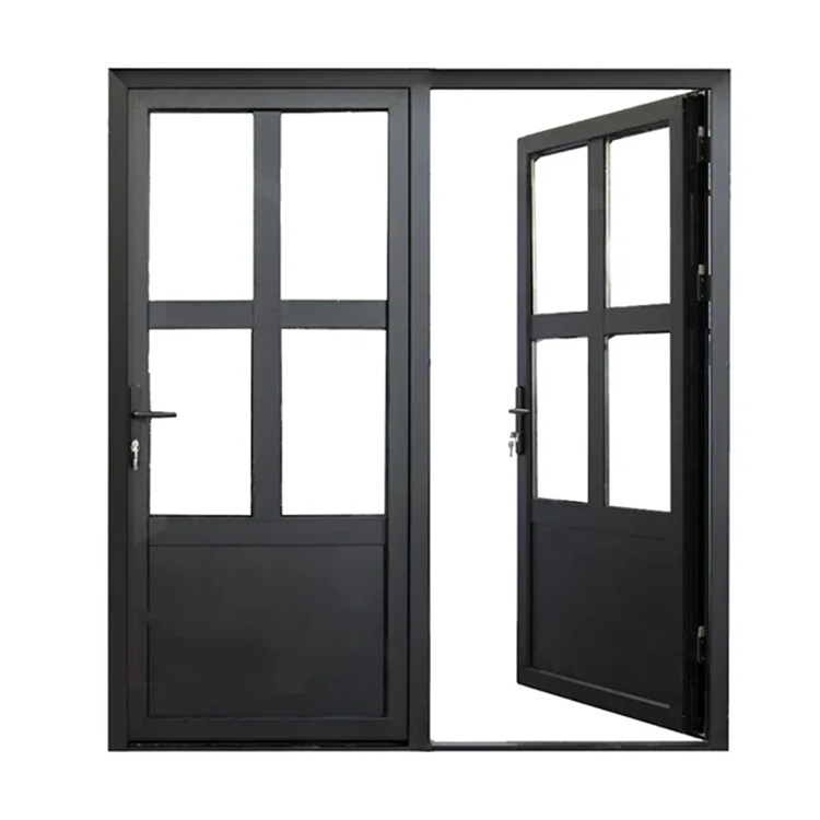
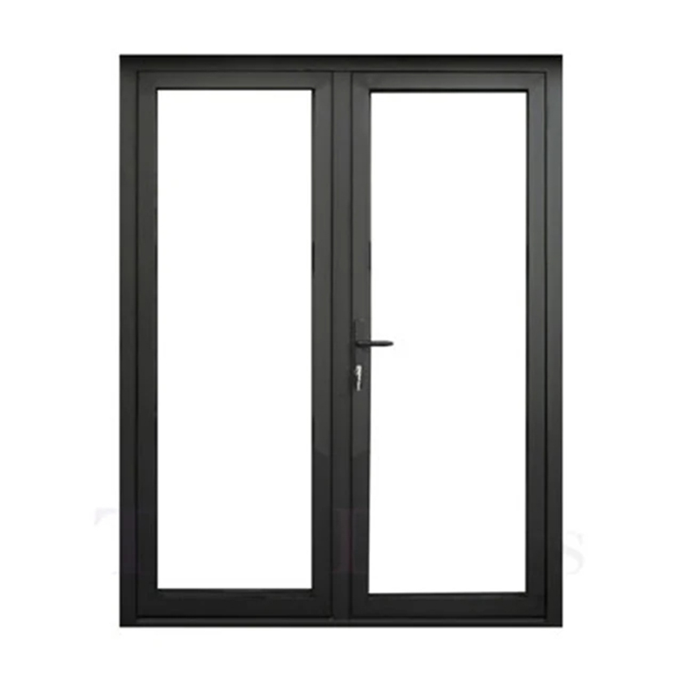
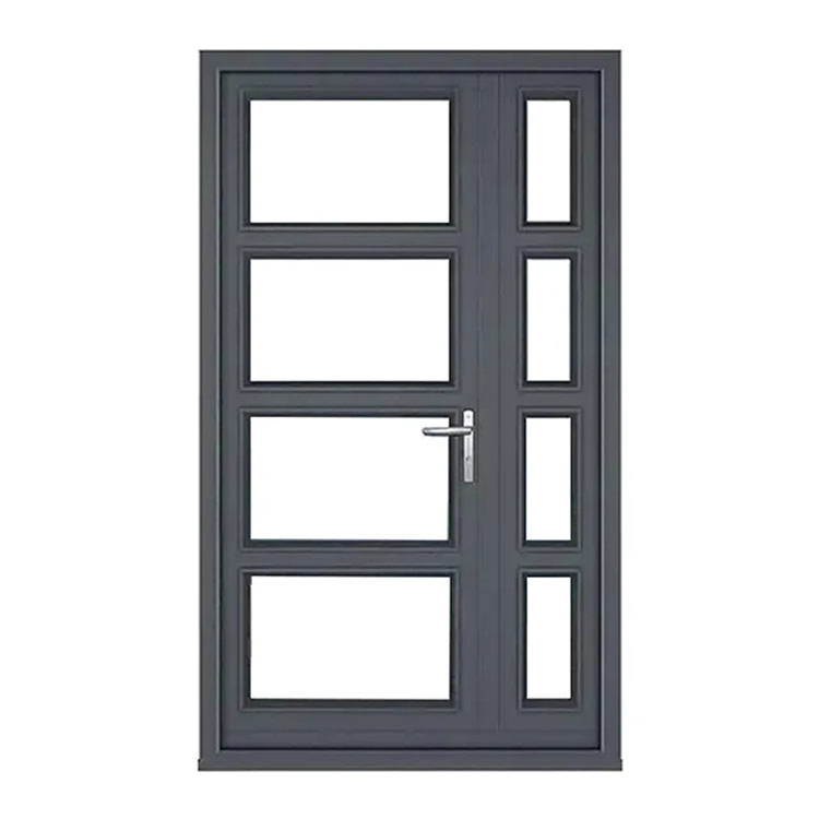
A typical hinged aluminum door may require:
Lever handle, pull handle, or panic hardware
Escutcheons or backplates
Spindle and fixing screws
Lockcase or gearbox
Cylinder and cylinder-retaining screw
Faceplate
Latch and deadbolt
Top and bottom extension rods
Hooks, rollers, bolts, or mushroom locking points
Keeps or strike plates
Hinges, pivots, or concealed hinge assemblies
Door closer or floor spring
Threshold and sealing accessories
Flush bolts for inactive leaves
Door coordinator for paired leaves
Restrictor or hold-open device
Fasteners, packers, and adjustment hardware
Each item must connect to the door profile, handing, leaf mass, opening direction, finish, and approved test configuration.
Build an aluminum window hardware tree
A typical casement or tilt-and-turn window may require:
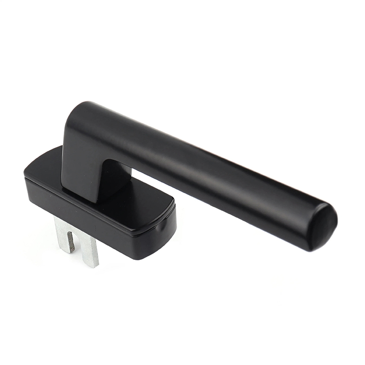
Operating handle
Spindle
Gearbox or espagnolette
Connecting rods
Corner drives
Locking cams, rollers, or mushroom pins
Keeps
Friction stays, hinges, or tilt-and-turn hinge sets
Sash lifter
Mishandling device
Restrictor or child-safety device
Anti-slam or anti-lift component
Ventilation position component
Fasteners and packers
Cover caps
Installation templates
The handle is only the visible part. The system underneath decides whether the sash compresses evenly, resists water, operates without binding, and remains serviceable.
The 14 BOM Fields I Would Refuse to Leave Blank
A component description alone is weak evidence. Every row should carry enough information for engineering, purchasing, quality control, assembly, and after-sales teams to identify the same part without interpretation.
BOM field
Required information
What goes wrong when it is missing
Item number
Unique BOM line reference
Drawings and inspection reports cannot reference the same component
Internal part number
Controlled company SKU
Purchasing creates duplicate or unofficial items
Supplier part number
Exact manufacturer code
Reorders depend on names, photographs, or memory
Revision
Drawing or specification revision
Old and new versions become mixed
Component description
Functional, unambiguous name
“Lock” or “hinge” means different things to different teams
Application
Door/window type, opening mode, location
A visually similar part is used in the wrong system
Strength and corrosion behavior become unpredictable
Finish
Color, process, coating class, gloss, texture
Components do not match or survive exposure
Performance requirement
Load, torque, cycles, security, corrosion, force
Supplier substitutes a cheaper but weaker part
Verification record
Drawing, report, certificate, inspection method
“Approved” cannot be proven later
Service reference
Replacement SKU and compatibility notes
Field repairs require complete hardware replacement
My hard rule is simple: when a blank field could change fit, function, safety, appearance, compliance, or reorder consistency, it is not an optional field.
Specify Interfaces, Not Just Components
Hardware selection fails at interfaces.
A high-quality handle can still fail when its spindle is too short. A strong hinge can loosen when the screw engagement is inadequate. A correctly machined gearbox can bind when coating thickness or profile tolerances move the installation plane.
So every major hardware item should have an interface specification.
Handle and spindle interface
Record:
Spindle section, such as 7 × 7 mm or 8 × 8 mm
Spindle material
Spindle length
Engagement depth
Handle fixing centers
Rose or backplate dimensions
Screw diameter, pitch, grade, and length
Operating angle
Return-spring requirement
Projection and clearance
Handing
Cylinder spacing, where applicable
Never approve “spindle included.” Included is not a specification.
Lockcase and gearbox interface
Record:
Backset
Handle-to-cylinder center distance
Faceplate width and thickness
Faceplate shape
Lockcase depth
Spindle follower size
Screw-hole locations
Latch direction
Deadbolt or hook projection
Rod connection type
Operating travel
Required torque
Keeper engagement
Profile machining reference
For multi-point systems, also document the locking-point count, center positions, total faceplate length, extension-rod lengths, and permissible adjustment at every keep.
Hinge and friction-stay interface
Record:
Maximum tested or approved sash mass
Sash width and height range
Opening angle
Stack height
Track length
Mounting-hole pattern
Fastener specification
Edge distances
Required reinforcement
Adjustment range
Material pairing
Corrosion exposure
Lubrication instructions
A hinge catalog load rating is not automatically your system load rating. Geometry, fasteners, reinforcement, center of gravity, opening angle, and installation quality all interfere.
Material and Finish Specifications Must Be Measurable
“Aluminum alloy” is not enough.
Possible component materials include ADC12 die-cast aluminum, 6063-T5 extrusion, 6061-T6 machined aluminum, zinc alloy, 304 stainless steel, 316 stainless steel, carbon steel, brass, POM, PA66-GF30, EPDM, and other engineered materials. Those are examples, not interchangeable options.
A BOM should name the approved material or reference a controlled material specification.
The same discipline applies to finishes. “Black powder coating” tells the factory almost nothing.
Document:
Pretreatment process
Coating or plating system
Target color code or approved master sample
Gloss range
Texture
Film-thickness range
Adhesion requirement
Corrosion-test requirement
UV or weathering requirement
Approved touch-up method
Protected cosmetic surfaces
Packaging protection
I also add a galvanic-contact review whenever aluminum, stainless steel, plated steel, brass, or zinc-based parts meet in a wet or chloride-rich environment.
Pretty samples lie.
A finish may survive a conference table and fail after six months of salt air, alkaline cleaner, trapped water, packaging rub, or installer handling. That is why a useful aluminum window hardware list identifies the entire material stack, not merely the visible color.
Performance Evidence Belongs Inside the BOM
The BOM should point to evidence, not vague claims such as “heavy duty,” “weather resistant,” or “ADA style.”
Those phrases are sales language.
Accessibility cannot be reduced to a lever shape
The 2010 ADA Standards for Accessible Design require applicable operable parts to work with one hand, without tight grasping, pinching, or wrist twisting, and limit activation force to 5 lbf, or 22.2 N. A BOM for an accessible opening should therefore control the handle type, mounting location, operating force, closer setting, latch behavior, and complete installed configuration—not merely specify a lever.
And enforcement is not theoretical. A U.S. Department of Justice settlement involving AmericInn and Wyndham properties documented doors requiring 15 pounds of opening force and security hardware positioned 54 inches above the floor, while the referenced requirements called for a 5-pound maximum on applicable interior hinged doors and operable hardware between 34 and 48 inches. A sloppy door hardware checklist can become a legal defect schedule.
Window safety hardware deserves its own BOM classification
According to the CPSC’s 2026 National Window Safety Week release, an estimated 5,600 U.S. children aged 12 and under received emergency-department treatment after window falls in 2024, with roughly one-third hospitalized; the agency also identified at least 25 deaths among children in that age group from 2021 through 2023. Restrictors, guards, release mechanisms, and opening-control devices are not decorative options.
For safety-related rows, add:
Intended safety function
Applicable opening-size or travel limit
Release method
User-force requirement
Fastener and substrate requirements
Installation height or location
Inspection method
Warning label
Replacement interval
Applicable test or regulatory reference
Sealing performance depends on hardware geometry
The U.S. Department of Energy’s home energy checklist states that a typical home loses more than 25% of its heat through windows. Hardware is not the only factor, but keeper positions, locking-point distribution, hinge alignment, gasket compression, and sash support all affect whether the designed seal is achieved in production.
FEMA also maintains a Hurricane Ian recovery advisory specifically addressing water intrusion through windows and doors. The procurement lesson is obvious: a window or door should be treated as an integrated envelope assembly, not a pile of independently purchased components.
Before approving a BOM, I would route the configuration through a documented hardware compliance review for aluminum windows and doors. The page correctly focuses on matching labels, listings, reports, and installed configurations rather than trusting a certificate detached from the actual assembly.
Build the BOM in Seven Controlled Passes
Trying to complete the spreadsheet row by row is slow and unreliable. Build it in passes.
Pass 1: Define every system variant
Create a variant matrix before selecting hardware.
Possible variables include:
Door versus window
Opening type
Handing
Sash size
Sash mass
Profile series
Locking-point count
Cylinder type
Handle style
Finish
Security grade
Coastal versus inland exposure
Accessible versus standard configuration
Retail, project, or replacement packaging
This prevents one “universal” BOM from quietly covering incompatible products.
Pass 2: Create the functional breakdown
Break the hardware into functional groups:
Operation
Locking
Load support
Sealing and compression
Safety
Security
Installation
Appearance
Identification
Packaging and service
Every function needs an owner. If no component performs the function, the design may be incomplete. If two components perform the same function accidentally, the BOM may contain waste or conflict.
Pass 3: Map every part to the profile
Link each hardware row to:
Profile drawing
Machining drawing
Installation plane
Datum
Hole pattern
Minimum wall thickness
Reinforcement
Fastener engagement
Adjustment allowance
Do not let suppliers infer dimensions from a photograph.
Pass 4: Add CTQ characteristics
CTQ means critical to quality. These are dimensions or characteristics that can cause fit, function, safety, or appearance failures.
Examples include:
Backset
Spindle size
Handle centers
Faceplate width
Rod travel
Locking-point position
Keeper height
Hinge stack
Friction-stay length
Screw engagement
Coating thickness
Color difference
Operating torque
Opening force
Each CTQ should have a nominal value, tolerance, measurement method, sampling plan, and record owner.
Pass 5: Add procurement and supply data
Now add:
Supplier
Manufacturer
Country of origin
Minimum order quantity
Standard pack quantity
Tool ownership
Tool number
Sample lead time
Production lead time
Safety-stock target
Approved alternative
Last purchase price
Currency
Incoterm
Replacement risk
End-of-life status
Do not allow an approved alternative to remain verbal. A substitution is either engineered, validated, documented, and released—or it is not approved.
Pass 6: Attach the evidence pack
The BOM should reference the current versions of:
2D drawings
STEP or other 3D files
Installation drawings
Material declarations
Finish specifications
Inspection reports
Test reports
Certificates or declarations
Packaging drawings
Label artwork
Assembly instructions
Approved samples
Deviation approvals
Engineering change notices
A central hardware download and document library is useful because it brings CAD/BIM files, installation drawings, manuals, certificates, declarations, and packaging specifications into the same sourcing workflow.
Pass 7: Run a physical BOM audit
Build one complete unit.
Then disassemble it.
Count every separate item, including clips, washers, screws, covers, labels, shims, and consumables. Compare the physical pile against the BOM. Next, rebuild the unit using only the BOM, drawings, and instructions available to production.
No tribal knowledge. No engineer standing beside the line. No supplier sending a corrective voice message.
Can the assembly still be completed correctly?
A Practical Sample BOM Structure
The following simplified example shows the level of detail expected. Dimensions are illustrative and must not be copied into a live product without engineering validation.
Item
Component
Example specification
Qty.
CTQ check
Evidence
10
Casement handle
7 mm spindle interface, right-hand, black textured finish
22 mm backset, 7 mm follower, specified rod travel
1
Backset, follower fit, operating torque
Drawing and functional report
30
Extension rod
Cut length by sash-height matrix
2
Length, hole position, straightness
Cutting schedule
40
Locking cam
Adjustable roller or mushroom type
4
Cam position and adjustment range
Assembly drawing
50
Keeper
Profile-specific, adjustable
4
Engagement depth and fastener location
Profile interface drawing
60
Friction stay
Size and load rating matched to sash
2
Track length, stack height, opening angle
Load and application record
70
Restrictor
Opening limit defined by project requirement
1
Maximum travel and release action
Safety test reference
80
Fixing screw
Defined diameter, pitch, grade, coating, and length
12
Engagement depth and corrosion spec
Fastener specification
90
Cover cap
Material and color matched to approved sample
2
Fit and color
Cosmetic standard
100
Identification label
System, batch, and revision reference
1
Data accuracy and adhesion
Label artwork
Notice what is absent: “standard,” “suitable,” “high quality,” and “same as sample.”
Those words cannot be measured.
Revision Control Is Where Good BOMs Usually Collapse
Revision control wins.
When engineering changes a spindle length, keeper geometry, coating stack, screw length, or gearbox travel without updating every linked drawing, purchasing record, inspection plan, assembly instruction, service list, and package label, the company creates multiple unofficial products under one part number.
Who owns the change?
Every BOM should show:
BOM number
Current revision
Release date
Status
Change description
Reason for change
Affected variants
Old part disposition
Inventory disposition
Validation required
Approvals
Effective production batch
Supplier acknowledgement
Customer notification requirement
Never overwrite an old approved specification.
Release a new revision. Preserve the history. State whether old and new parts are interchangeable.
For custom programs, the OEM/ODM hardware development process provides a sensible sequence: requirements, DFM and tolerance review, prototypes, verification, pilot production, mass production, traceability, and controlled revisions. That is the right backbone for converting a BOM from a quotation tool into a repeatable manufacturing record.
The Final BOM Audit Checklist
Before release, I ask these questions:
Does every physical component have a BOM row?
Does every BOM row have an approved drawing or specification?
Are left- and right-hand components separated?
Are door and window variants separated?
Are quantities defined per finished assembly?
Are fasteners fully specified?
Are material and finish requirements measurable?
Are interface dimensions linked to profile drawings?
Are sash mass and hardware capacity matched?
Are safety devices treated as controlled components?
Are applicable operating-force requirements documented?
Are corrosion and exposure conditions stated?
Are test reports linked to the exact configuration?
Are approved substitutions documented?
Are packaging quantities and labels controlled?
Are replacement parts mapped?
Is revision history preserved?
Can production assemble the unit without verbal instructions?
Can purchasing reorder it two years later without guessing?
Can quality inspection reject a wrong part objectively?
One “no” is enough to stop release.
That may sound harsh. It is cheaper than recalling completed windows, sorting mixed inventory, re-machining aluminum profiles, or explaining to a project manager why the approved black handle does not operate the approved gearbox.
FAQs
What is a complete hardware BOM for an aluminum door or window system?
A complete hardware BOM for an aluminum door or window system is a revision-controlled technical list identifying every operating, locking, supporting, sealing, safety, installation, cosmetic, packaging, and service component required for one defined assembly, together with quantities, materials, finishes, interface dimensions, performance requirements, inspection criteria, and supporting documents.
It must cover the entire opening, not only visible hardware. The finished document should allow purchasing to order, production to assemble, quality control to inspect, and service teams to replace components without relying on memory or verbal explanations.
What should an aluminum door hardware BOM include?
An aluminum door hardware BOM should include handles, spindles, escutcheons, lockcases, cylinders, faceplates, latches, deadbolts, multi-point extensions, locking elements, keeps, hinges, closers, thresholds, flush bolts, restrictors, fasteners, packers, labels, packaging materials, interface dimensions, finish requirements, test references, quantities, revisions, and approved replacement-part numbers.
The precise list changes with door type. A hinged entrance door, lift-slide door, folding door, fire-rated opening, and paired commercial door do not share one valid universal BOM.
How do I prevent missing parts in an aluminum window hardware list?
The best way to prevent missing parts in an aluminum window hardware list is to create a functional hardware tree, build and disassemble a physical sample, count every component and consumable, map each item to a controlled drawing, and rebuild the unit using only the released BOM and instructions.
This catches the clips, screws, shims, cover caps, corner drives, safety devices, and packaging items that rarely appear in early quotations. It also exposes undocumented assembly knowledge before mass production begins.
What is the difference between a BOM and a fenestration hardware schedule?
A hardware BOM is a manufacturing and procurement record listing exact components, quantities, revisions, materials, interfaces, and verification requirements for a defined assembly, while a fenestration hardware schedule usually summarizes the hardware configuration assigned to each opening type, elevation, room, project mark, or architectural specification reference.
The schedule tells the project team what each opening needs. The BOM tells the factory exactly what must be purchased and assembled to produce it. Serious projects need both documents linked through controlled opening or system codes.
When should a door and window bill of materials be updated?
A door and window bill of materials should be updated whenever a component, supplier, material, finish, dimension, tolerance, quantity, test requirement, packaging method, label, machining pattern, installation instruction, approved alternative, or replacement relationship changes in a way that can affect fit, function, safety, appearance, compliance, cost, or reorder consistency.
Do not wait for the next annual review. Release the change before the new component enters production, define the effective batch, control remaining inventory, and record whether the old and new versions are interchangeable.
Turn Your Hardware List Into a Manufacturing System
Stop asking suppliers for “a complete set of hardware.”
A marked-up component BOM with supplier part numbers and revisions
A compatibility and DFM review identifying missing data or interface risks
A physical sample kit supported by drawings, inspection criteria, and a controlled change log
Do that before approving mass production.
A complete hardware BOM will not make a weak design strong. But it will expose weak assumptions while they are still cheap enough to correct—and that is exactly what a professional aluminum door or window program needs.