Looking for hardware solutions that meet European / American standards?
Use this guided inquiry modal to move from a generic quote form to a clearer technical conversation. Buyers can choose whether they need pricing, CAD / 3D files, or OEM / ODM support before sharing contact details.
Compatibility-first design across door / window systems
Repeatable production with clear inspection checkpoints
Documentation and change control for long-running programs
Responsive engineering support for fit and field feedback
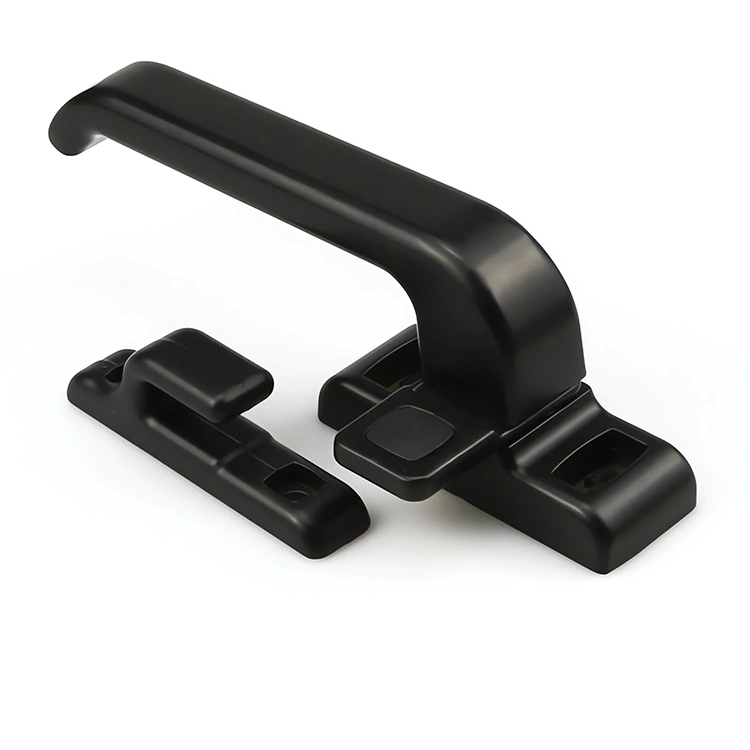
A sliding door handle mounted on a light wardrobe panel performs a completely different job from one fitted to a 120 kg glazed entrance panel, even when both products look nearly identical in a supplier catalog and share the same black powder-coated finish.
So why does the industry still buy handles by appearance?
I see the same error in specification after specification: the buyer chooses a handle first, then tries to force the panel, stile, spindle, lock body, keeper, and mounting screws to cooperate. That order is backward.
A sliding door handle is an operating interface. It transfers force from the user into the panel or locking system. Its performance therefore depends on three connected variables:
Panel weight and measured operating force
Available stile width and internal profile geometry
Lock type, spindle arrangement, and keeper position
Ignore one, and the handle may loosen, bind, scrape the fixed panel, fail to retract the hook, or become nearly impossible for some users to operate.
Panel Weight Is Not the Same as Handle Load
Here is the hard truth: a panel’s mass does not tell you how hard the user must pull.
A well-aligned 150 kg panel on correctly sized rollers may move more easily than a 45 kg panel running on damaged bearings, a dirty track, distorted framing, or badly compressed weather seals. The handle reacts to operating resistance, not merely the number printed in the glass or door schedule.
For accessible sliding and folding doors, the U.S. Access Board sets a maximum continuous opening force of 5 lbf, or 22.2 N. The force is measured after disengaging the latch or other holding device. Door hardware itself must also operate with no more than 5 lbf, and the operating part should not demand tight grasping, pinching, or wrist twisting. The Access Board’s door and gate guidance explains the measurement method and force distinction.
That standard exposes a common purchasing myth. A “heavy-duty” handle is not automatically suitable for a heavy panel. The full assembly must produce an acceptable opening force.
What Panel Weight Actually Changes
Greater panel mass usually increases the consequences of poor specification. It can raise:
Starting resistance when rollers or tracks are undersized
Momentum as the panel approaches the jamb
Shock loading when users slam the door
Pull-out stress on the handle fixings
Wear at the roller, track, stopper, and soft-close interfaces
The need for a deeper, more secure handhold
The risk of handle flex or base movement during aggressive use
But a handle should not be asked to compensate for a bad sliding system.
That matters.
When a user must pull harder because the rollers are binding, every extra newton passes through the handle base, screws, inserts, and extrusion wall. Increasing handle thickness may hide the symptom for a while. It does not fix the track.
A Practical Sliding Door Handle Selection Matrix
The following weight bands are early-stage procurement screens, not universal product ratings or building-code limits. I use them to decide what evidence a supplier must provide before a sample is approved.
Panel Weight Screening Band
Likely Handle Direction
Mounting Approach
Suitable Lock Directions
Evidence I Would Request
Up to 60 kg
Recessed pull, compact lever, surface pull
Profile screws, concealed fixings, or through-fixing where possible
Non-locking pull, compact surface lock, single hook mortise lock
Mounting dimensions, operating test on intended profile, pull or static-load result
Stable attachment without sharp edges or finger traps
Low-force latch or lock mechanism
5 lbf verification, mounting height, clearance and usability review
These bands do not replace testing. They identify when testing becomes more demanding.
For example, a 50 kg residential panel with poor rollers may impose greater daily stress on its handle than a professionally engineered 100 kg commercial panel. And a 90 kg lift-slide panel may require substantial handle torque to lift the sash from its seals even though horizontal movement becomes easy after the mechanism is engaged.
Different motion. Different job.
Start With Measured Operating Force, Not the Catalog Weight Claim
The most useful test is simple: install the intended rollers, panel, track, seals, lock, keeper, and handle on the intended profile. Then measure force throughout the complete opening and closing stroke.
Do not test only the first 100 mm.
A panel may start easily and then bind at mid-travel because the track is not level. It may move smoothly until the handle approaches the interlock stile, where insufficient projection traps the user’s fingers. It may close well but require a sharp final pull to engage a hook lock against a badly positioned keeper.
I would record at least four conditions:
Initial breakaway force
Continuous sliding force
Final closing or seal-compression force
Lock activation or release force
The U.S. Justice Department has repeatedly treated excessive door force and inaccessible hardware as real compliance failures, not cosmetic defects. In a Butler County, Missouri settlement attachment, inspected doors reportedly required 9, 10, 14, 15, 16, and 17 pounds of opening force in different locations; remediation called for no more than 5 pounds and hardware that did not require tight grasping, pinching, or wrist twisting. The Butler County findings are a blunt reminder that a product can open and close while still being unacceptable.
My opinion? Any serious commercial supplier should be willing to discuss force in newtons, not just panel weight in kilograms.
Stile Width Determines Whether the Handle Can Physically Survive
The phrase “60 mm stile” sounds useful. Often it is not.
A nominal stile width does not equal the mounting width available to the handle. Inside that extrusion, you may also have:
A glass pocket and glazing gasket
Screw bosses
Thermal-break material
Reinforcement
A mortise lock case
A spindle follower
Cylinder clearance
Drainage or fabrication features
Interlock geometry
Panel-overlap clearance
The visible face could be 60 mm wide while the safe fixing zone is less than half that.
Before choosing any sliding door handle configuration, check its base width, cutout, fixing centers, handle projection, operating direction, panel overlap, and lock interface against a full extrusion section. CHIER’s sliding-handle category itself distinguishes recessed pulls, fold-out handles, surface levers, clearance, projection, and lock interfaces rather than treating all sliding handles as interchangeable.
Narrow-Stile Screening Bands
These are practical RFQ screening bands, not legal classifications:
Below 35 mm of usable mounting face: Treat the stile as genuinely narrow. Look at recessed edge pulls, slim backplates, fold-out grips, concealed fixings, or a custom handle-lock package. A standard lever rose is usually the wrong starting point.
35–55 mm of usable mounting face: Compact levers and narrow mortise-lock furniture become possible, but screw bosses, spindle position, glass-pocket depth, and edge distance still control the design.
Above 55 mm of usable mounting face: More handle bases can fit, yet wider does not automatically mean stronger. Thin extrusion walls and poorly located fixings still fail.
Notice the phrase usable mounting face. That is the number that belongs in the request for quotation.
The Edge-Distance Problem Buyers Miss
A narrow base may fit visually while its screws sit too close to the profile edge or glass pocket. That can create local deformation, stripped threads, coating damage, or cracking around a machined cutout.
And there is another trap: narrowing the base often reduces the distance between mounting screws. That can make the handle more prone to rocking under an off-axis pull.
A long lever magnifies the problem.
The supplier should therefore confirm the complete load path from the user’s hand to the extrusion—not just whether two holes can be drilled.
Match the Sliding Door Handle to the Lock Type
Handle selection becomes more technical once the handle operates a lock.
A pull-only handle transfers linear force into the panel. A mortise-lock handle may transmit rotational torque through a spindle. A multipoint system must move several connected locking elements. A lift-slide handle may first raise a heavy sash and release gasket compression before the panel can move.
Calling all four products “sliding door handles” creates expensive confusion.
Pull-Only or Non-Locking Handle
A pull-only handle has no spindle or lock-drive function. Its main requirements are:
Sufficient grip depth
Safe finger clearance
Adequate attachment strength
Acceptable projection at the interlock
No interference with the fixed panel, wall pocket, insect screen, or frame
For pocket doors and overlapping panels, a recessed or fold-out pull may be necessary. But very shallow recesses can become fingertip hooks rather than usable grips.
That is poor design dressed as minimalism.
Surface-Mounted Sliding Lock
A surface lock or slide bolt sits on the face of the profile and engages a separate keeper. It can suit simple windows, secondary panels, cabinets, or other applications where the mounting surface and keeper position are available.
The sliding lock options should be compared by body dimensions, mounting-hole spacing, bolt direction, bolt travel, keeper height, and operating orientation. A keeper that is 2 mm out of line can turn an otherwise acceptable lock into a daily fight.
Mortise Hook Lock
A mortise hook lock places its lock body inside the stile. This reduces visible bulk but consumes internal profile space.
The handle must match:
Backset
Spindle size and shape
Handle-to-cylinder center distance
Lock-case depth and height
Faceplate width
Hook direction and travel
Keeper position
Left- or right-hand operation
Required rotation angle
A narrow-stile sliding door handle with a mortise lock should be developed as a matched assembly. Mixing a generic handle, an unrelated spindle, and a convenient lock body is not engineering. It is gambling.
Multipoint Mortise Lock
A multipoint system links a central gearbox to two or more locking points. The handle must deliver enough torque to move the complete mechanism without excessive flex, lost motion, or spindle deformation.
CHIER’s multipoint door lock range identifies backset, handle-to-cylinder centers, faceplate dimensions, spindle followers, locking-point positions, and keeper layout as matching variables. Those are the dimensions that belong in the approval drawing.
A wide handle base does not rescue an incompatible gearbox.
Lift-Slide Locking System
A lift-slide handle performs mechanical work before the door begins to travel. Rotating the handle activates a gearbox that lifts the sash, unloads the seals, and places the panel onto its running position.
This arrangement usually requires:
A longer lever
A defined operating arc
Strong spindle engagement
Controlled end stops
Adequate clearance from the frame
Verified torque through the complete movement
Clear locked, sliding, and lowered positions
Never substitute a conventional mortise-lock lever because it “looks close.” The internal load and travel may be completely different.
Handle Geometry Is an Ergonomic Specification
The handle must fit the user as well as the door.
A University of Michigan human-factors study examined cylindrical handles from 38 to 83 mm in diameter. It found that the ratio between handle diameter and hand length explained 62% of the variance in grip force, 57% in normal force, and 71% in contact area. The researchers also found that average total normal force was 2.3 times the split-cylinder grip-force measurement. The PubMed study on handle size and grip shows why grip geometry should not be reduced to styling.
This does not mean a sliding door pull should be 38, 58, or 83 mm in diameter. The tested objects were cylindrical research handles, not architectural product recommendations.
The useful conclusion is broader: hand size and handle dimensions interact. One grip profile will not feel equally secure to every user.
For public or age-inclusive applications, I prefer:
A lever or pull that can be used with one hand
Enough clearance for the fingers to wrap without scraping the stile
Rounded contact edges
A surface that does not become dangerously slippery
An operating motion that avoids tight pinching
A lock action that gives clear mechanical feedback
Research on designing for older adults similarly recommends levers over knobs that must be gripped and turned, particularly where reduced grip strength, stiffness, tremor, or coordination may affect use. The published design guidance supports simple operating movements and larger, easier-to-use controls.
Safety Glass Does Not Excuse Weak Hardware
For glazed sliding panels, handle engineering and glazing safety sit in the same risk chain.
The U.S. Consumer Product Safety Commission’s mandatory architectural-glazing standard covers glazing used in interior and exterior doors and patio-type sliding glass doors. In 2016, the CPSC voted 5-0 to update the testing procedures by incorporating the then-current ANSI Z97.1-2015 procedures while maintaining the existing product scope. The CPSC architectural glazing announcement explains that coverage.
But safety glazing does not make bad handle placement acceptable.
A handle mounted too close to the glass pocket can interfere with glazing components. A sharp-edged recessed pull can create a contact hazard. A weak lock or loose handle can encourage users to jerk the panel, increasing uncontrolled movement and impact at the jamb.
The Specification Data I Would Demand Before Approval
A professional sliding door hardware submission should include more than a product photo and finish chip.
Panel and Movement Data
Panel width and height
Total assembled panel mass in kilograms
Glass build-up and frame material
Roller model, quantity, and rated capacity
Track material and geometry
Measured opening and closing force
Soft-close or damper information
Stop position and expected closing speed
Stile and Mounting Data
Full extrusion cross-section
Nominal and usable stile width
Wall thickness at each fixing point
Handle cutout dimensions
Mounting-center dimensions
Fastener type, diameter, and engagement depth
Reinforcement or threaded-insert details
Glass-pocket and gasket clearance
Interlock and panel-overlap clearance
Handle and Lock Data
Overall handle dimensions
Projection from panel face
Grip clearance
Spindle section and length
Rotation angle
Backset
Handle-to-cylinder center distance
Lock faceplate width and thickness
Hook, bolt, or shoot-bolt travel
Keeper dimensions and adjustment range
Handing
Keying requirements
Material and finish specification
Verification Data
Static pull or attachment test
Operating-torque test
Cycle-life target
Inspection interval
Acceptable looseness or free play
Finish adhesion or corrosion test where required
Sample quantity
Pass-and-fail criteria
Test fixture and installed profile
CHIER’s quality-control and hardware-testing process correctly states that different products should not be approved under one generic test claim. It calls for the applicable model, installation condition, mating components, load or torque, cycle period, sample quantity, and pass-and-fail criteria to be agreed before testing.
That is the right mindset. “Tested” means almost nothing until someone tells you how.
Common Sliding Door Handle Failures and Their Real Causes
The Handle Becomes Loose
Likely causes include insufficient screw engagement, thin profile walls, poor inserts, fixing holes that have elongated, an undersized mounting pattern, or users applying excessive force because the panel does not run properly.
Replacing the handle with a heavier casting may postpone failure. It may also transfer the damage into the extrusion.
The Handle Hits the Fixed Panel
Projection, panel overlap, interlock geometry, or mounting position was not checked in the fully open and fully closed positions.
This mistake is common with deep-grip heavy-duty sliding door handles. The grip is comfortable in isolation but physically incompatible with the opening system.
The Lock Is Difficult to Engage
The panel may be out of square, the keeper may be misaligned, the hook travel may be wrong, the seals may be overcompressed, or the handle may not produce enough usable torque.
Do not immediately blame the lock body.
The Lever Sags or Feels Loose
Possible causes include spindle clearance, follower wear, weak return components, excessive gearbox resistance, loose base fixings, or handle material flex.
A cosmetic cover can hide the screws. It cannot remove mechanical play.
The Recessed Pull Is Painful to Use
The finger pocket may be too shallow, too narrow, sharply edged, or positioned where the user can only pull with the fingertips.
Flush appearance has a cost. Someone still has to move the door.
How I Would Approve a New Handle Program
I would begin with the profile and operating system, not the supplier’s bestseller list.
First, send the door manufacturer’s extrusion drawing, assembled panel weight, roller information, lock requirements, overlap dimensions, and target market. Then shortlist handle structures that physically fit.
Second, produce samples using the intended spindle, lock, keeper, screws, inserts, and profile. A loose bench sample is not enough.
Third, measure movement and lock operation. Record newtons, torque, travel, interference, wobble, and user clearance.
Fourth, perform the agreed static and repeated-operation checks.
Finally, lock the approved drawing revision, bill of materials, finish reference, inspection plan, and golden sample before volume production.
For custom programs, CHIER’s OEM and ODM hardware development process starts with the profile section, mating hardware, critical dimensions, drawings, samples, and acceptance criteria before moving through feasibility review, sample verification, pilot production, and controlled mass production.
That process is slower than picking a handle from a photograph.
It is also cheaper than replacing thousands of incompatible units.
FAQs
What is a heavy-duty sliding door handle?
A heavy-duty sliding door handle is a handle assembly whose grip, base, fasteners, spindle, and lock interface have been verified for the panel’s measured operating force, expected cycle count, user population, and mounting profile; panel mass alone does not make a handle heavy duty, and a thick casting without attachment evidence proves very little.
For heavier panels, request test evidence for the handle on the intended extrusion. The fixing system often matters more than the visible handle body.
What sliding door handle works with a narrow stile?
A sliding door handle for a narrow stile is a compact lever, recessed pull, edge pull, or fold-out handle whose base, cutout, screws, spindle, and lock body fit inside the usable profile envelope without entering the glass pocket, weakening the extrusion edge, interfering with reinforcement, or colliding with the overlapping panel.
Do not specify it from nominal stile width alone. Send the full profile cross-section and mark the glass, gasket, screw bosses, reinforcement, and lock cavity.
Can a sliding door handle be used with any mortise lock?
A sliding door handle cannot be assumed to work with every mortise lock because the handle and lock must match in backset, spindle section, spindle length, rotation, handle-to-cylinder centers, faceplate position, handing, hook travel, and required operating torque, while the combined assembly must also fit inside the stile and align with its keeper.
The safest route is a documented handle-lock-keeper set or a compatibility drawing approved by both suppliers.
What is the best sliding door handle for heavy panels?
The best sliding door handle for heavy panels is a deep, securely mounted pull or engineered operating lever selected from measured panel force, grip clearance, mounting strength, lock torque, stile geometry, and expected cycles, with through-fixing or reinforced attachment where needed and full-system testing on the intended rollers, track, profile, seals, lock, and keeper.
A longer or thicker handle is not automatically better. Excessive projection can collide with adjacent panels, while an overly long lever can magnify loads at weak mounting points.
How do you choose a sliding door handle?
Choose a sliding door handle by documenting the assembled panel weight, measured sliding force, usable stile width, panel overlap, grip clearance, mounting structure, lock type, spindle dimensions, keeper position, user-accessibility needs, and cycle target, then test a complete sample on the intended profile rather than approving the handle as an isolated component.
The sequence matters: application first, geometry second, lock interface third, appearance last.
Send the Profile Drawing Before Choosing the Handle
Do not begin your next sliding door handle project with a finish, catalog image, or vague request for something “heavy duty.”
Begin with evidence.
Prepare the panel weight, extrusion section, mounting zone, roller system, lock type, spindle dimensions, keeper layout, overlap clearance, target opening force, finish, annual quantity, and testing requirement. Then submit the package through CHIER’s door and window hardware project inquiry.
Ask for three things in return:
A dimensional compatibility review
A complete handle-lock recommendation
A sample and verification plan tied to your actual panel
A sliding door should feel easy because the system is engineered correctly—not because the user has learned to pull harder.