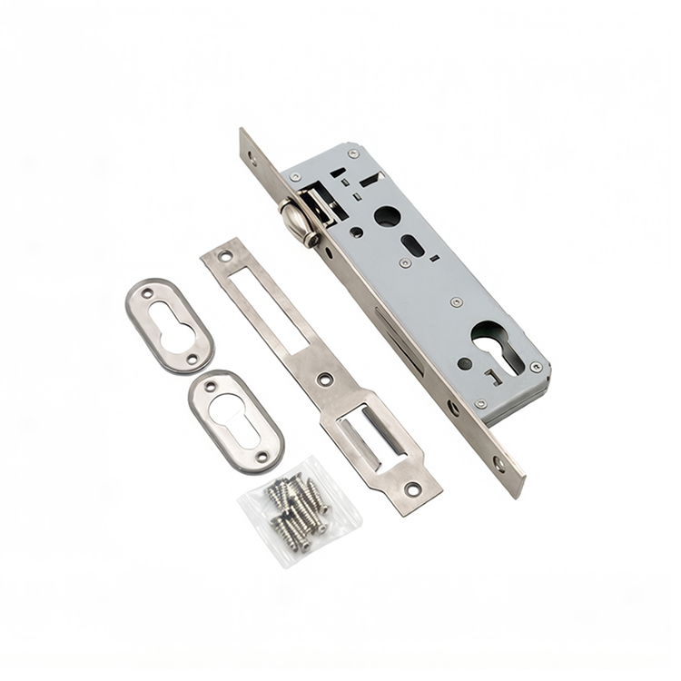
Looking for hardware solutions that meet European / American standards?
Use this guided inquiry modal to move from a generic quote form to a clearer technical conversation. Buyers can choose whether they need pricing, CAD / 3D files, or OEM / ODM support before sharing contact details.
Compatibility-first design across door / window systems
Repeatable production with clear inspection checkpoints
Documentation and change control for long-running programs
Responsive engineering support for fit and field feedback
To measure a multipoint door lock, record the backset, PZ centres, faceplate width and length, spindle size, handle fixing centres, overall strip length, and the exact position of every hook, roller, bolt or shootbolt.
That is the direct answer.
But here is the hard truth: backset and PZ alone will not reliably identify a replacement multipoint lock, because two mechanisms can share those headline dimensions while using different faceplates, gearboxes, hook positions, spindle sizes, connectors, keeps and operating sequences.
Why gamble?
I treat a multipoint lock as a coordinated door-edge mechanism, not a long strip of metal with a gearbox attached. The door profile, handle, cylinder, lockcase, faceplate, locking points and frame keeps all have to agree.
A near match is usually a bad match.
The Multipoint Lock Measurements That Actually Matter
A proper measurement record should describe the whole locking system. The official FUHR multipoint locking system measurement form, for example, asks for faceplate length and width, backset, centres, follower size, handle height, upper and lower lock distances, faceplate design and door direction. It does not ask buyers to send one blurry photograph and hope for the best.
Use this table as your working specification:
Measurement
Where to Measure
Example Manufacturer Values
What Happens If It Is Wrong
Backset
Faceplate edge to spindle centre
FUHR documents show options from 25 mm to 80 mm; one ASSA ABLOY lock family lists 55 mm to 100 mm
Handle and cylinder preparation will not align with the gearbox
PZ centres
Spindle centre to cylinder or key-opening centre
72 mm and 92 mm appear in FUHR documentation; other product families use different centres
Existing handles and escutcheons will not fit
Faceplate width
Across the metal strip on the door edge
Flat and U-shaped faceplates exist; one ABLOY model uses a 24 mm faceplate
The strip may not enter the routed channel or sit flush
Faceplate length
Top end to bottom end of the strip
Fully model-dependent
Screw holes, end positions and door-edge coverage may differ
Spindle follower
Across the square spindle opening
FUHR lists 8 mm, 9 mm and 10 mm options
The handle spindle may be loose or may not enter
Handle fixing centres
Centre of upper handle screw to centre of lower screw
Handle-dependent
The handle backplate cannot be reused
Upper and lower lock positions
Spindle centre to each hook, roller or bolt centre
Model-dependent
Locking points will miss the frame keeps
Gearbox depth
Faceplate rear to deepest gearbox point
Profile-dependent
The gearbox may strike reinforcement, glass or the profile wall
Overall strip length
Top of faceplate to bottom
Model-dependent
The replacement may require cutting or may be too short
Handing and operation
Viewed from the opening side and tested with the door open
Left, right, reversible, lever-operated, key-operated or automatic
Latch, hooks or panic functions may operate incorrectly
The numbers above are examples from manufacturer documentation, not universal standards. That distinction matters. ASSA ABLOY publishes different backsets, faceplate dimensions and handle-to-cylinder distances across its lock families, which is exactly why “it looks about right” is not an acceptable procurement method.
Remove and Inspect the Lock Before Measuring
You can take some multipoint lock measurements while the mechanism remains installed. You will get a much more reliable result after removing it.
Tools to Prepare
Use a steel rule, tape measure, vernier calliper, screwdriver set, masking tape, permanent marker and a phone camera. A ruler with a worn or damaged zero point belongs in the bin.
Millimetres only.
Record each dimension as you take it, and photograph the measuring tool against the component. That gives a supplier something verifiable rather than a handwritten number with no visible reference point.
A Safe Removal Sequence
Open the door and keep it open throughout the inspection.
Photograph the handle, cylinder, faceplate and locking points before removing anything.
Remove the cylinder-retaining screw from the faceplate.
Turn the key slightly until the cylinder cam aligns, then slide the cylinder out.
Remove the handles and spindle.
Remove the faceplate screws from top to bottom.
Withdraw the mechanism carefully without bending the strip.
Lay it on a flat surface beside a steel rule.
Do not close the door with the lock or cylinder removed. And do not operate an unsupported gearbox aggressively; some mechanisms can move out of sequence when tested away from their normal door and keeper positions.
How to Measure the Multipoint Door Lock Backset
The multipoint door lock backset is the horizontal distance from the front edge of the faceplate to the exact centre of the square spindle follower.
Measure from centres.
Place the lock flat, extend an imaginary line through the centre of the spindle opening, and measure at 90 degrees to the outer face of the faceplate; if you measure diagonally, from the lockcase edge, or from the visible edge of the door instead, the resulting number may be wrong even though it looks plausible.
Would you order a production part from a plausible number?
Common backsets depend heavily on the door system and product family. The FUHR measurement form includes 25, 28, 30, 35, 40, 45, 50, 55, 65 and 80 mm reference options, while ASSA ABLOY documentation shows other lock families reaching 100 mm.
Do not round 28 mm to 30 mm. Do not call 45 mm “about 45.” Write the actual result.
Backset Measurement Mistakes
The most common errors are:
Measuring from the door edge instead of the faceplate edge
Measuring to the side of the spindle hole instead of its centre
Including the thickness of a removable trim piece
Measuring a bent or twisted lock strip
Assuming every lock from the same brand uses one backset
A 2 mm error is not cosmetic. It changes where the gearbox sits inside the profile.
How to Take a PZ Centres Measurement
PZ is the vertical centre-to-centre distance between the square spindle follower and the centre of the euro-profile cylinder or key opening.
Measure from the middle of the spindle to the middle of the circular cylinder section. Do not measure to the top of the euro-profile cut-out, the bottom of the keyhole or the edge of the handle plate.
PZ is not the handle screw spacing.
That confusion creates a steady stream of incorrect orders because both dimensions are described casually as “centres.” On many residential systems, the PZ may be 72 mm or 92 mm, but those numbers are not a licence to guess. FUHR’s own measurement documentation lists both, while ASSA ABLOY publishes other centre dimensions for specialised lockcases.
For a reliable PZ centres measurement:
Mark the exact centre of the square follower.
Mark the rotational centre of the cylinder.
Measure vertically between the two marks.
Repeat the measurement twice.
Compare it with the handle backplate geometry.
When the lock remains installed, remove the handles first. Measuring through decorative handle plates adds visual error and can hide offset holes.
Measuring Door Lock Faceplate Size and Shape
The faceplate is the long metal strip visible along the opening edge of the door. Record its width, overall length, thickness and shape.
Width alone is insufficient.
A flat faceplate and a U-shaped faceplate may carry similar gearboxes, yet require different door-edge preparation. The FUHR measurement sheet explicitly separates flat and U-shaped designs, while ASSA ABLOY warns in its technical catalogue that certain U-faceplate versions alter the effective backset by 1 mm. That tiny note is exactly the kind of detail that disappears in marketplace listings.
Faceplate Width
Measure straight across the visible front surface. Use callipers when the difference between two likely options is small.
Do not include the folded sides of a U-shaped strip when recording its front width. Instead, write all three dimensions, such as:
24 mm front × 6 mm return × 1.5 mm material thickness
Faceplate Length
Measure from the physical top end to the physical bottom end. Do not stop at the last screw or locking point.
Also record whether the strip is:
One-piece
Extendable
Sectional
Designed to be cropped
Connected to separate shootbolts
Joined to upper and lower extensions
A replacement strip can sometimes be shortened, but that does not mean every strip should be cut. Cropping through a linkage channel, screw position or stamped guide can ruin the mechanism.
What “Centres” Means on a Multipoint Lock
The word “centres” is dangerously vague. In a complete multipoint locking system, it may refer to at least three different measurements.
PZ Centres
This is the spindle-to-cylinder measurement described above.
Handle Fixing Centres
This is the centre-to-centre distance between the screws that hold the external and internal handle plates together.
Measure each screw from its centre. Also note whether a fixing screw passes above the spindle, below the cylinder or through the lockcase.
Never assume that a handle with the correct PZ has the correct fixing centres. CHIER’s guide to multipoint door locks and matching interfaces treats backset, handle-to-cylinder centres, spindle follower, faceplate dimensions and locking-point positions as separate selection fields for good reason.
Locking-Point Centres
These measurements locate the hooks, rollers, mushrooms, bolts and shootbolt connections along the faceplate.
Choose one fixed datum. I recommend the spindle centre.
Record:
Spindle centre to upper hook centre
Spindle centre to lower hook centre
Spindle centre to every roller or mushroom cam
Spindle centre to auxiliary deadbolts
Spindle centre to top and bottom shootbolt connections
Projection direction and travel of each locking element
Write upper dimensions as positive numbers and lower dimensions as negative numbers, or label them clearly as “above spindle” and “below spindle.” Consistency beats clever notation.
How to Measure Hooks, Rollers and Bolts
Locking-point type matters as much as position.
A hook bolt must enter the correct keeper slot and pull behind it. A roller cam compresses the door toward the seal. A mushroom cam engages a shaped security keep. A shootbolt travels vertically into the head or threshold.
Those parts are not interchangeable.
For hook locks, measure:
Hook centre position
Hook width
Hook projection
Direction of hook travel
Distance between hooks
Keeper opening dimensions
Available adjustment
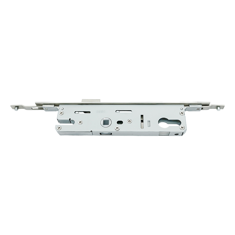
The twin-hook multipoint lock example demonstrates why hook spacing, projection, operating direction and keeper geometry have to be checked alongside backset and PZ.
For rollers, record the roller diameter, eccentric adjustment and distance from the faceplate. A 10 mm roller sitting 1.5 mm too far from the strip can change gasket compression or prevent the door from closing cleanly.
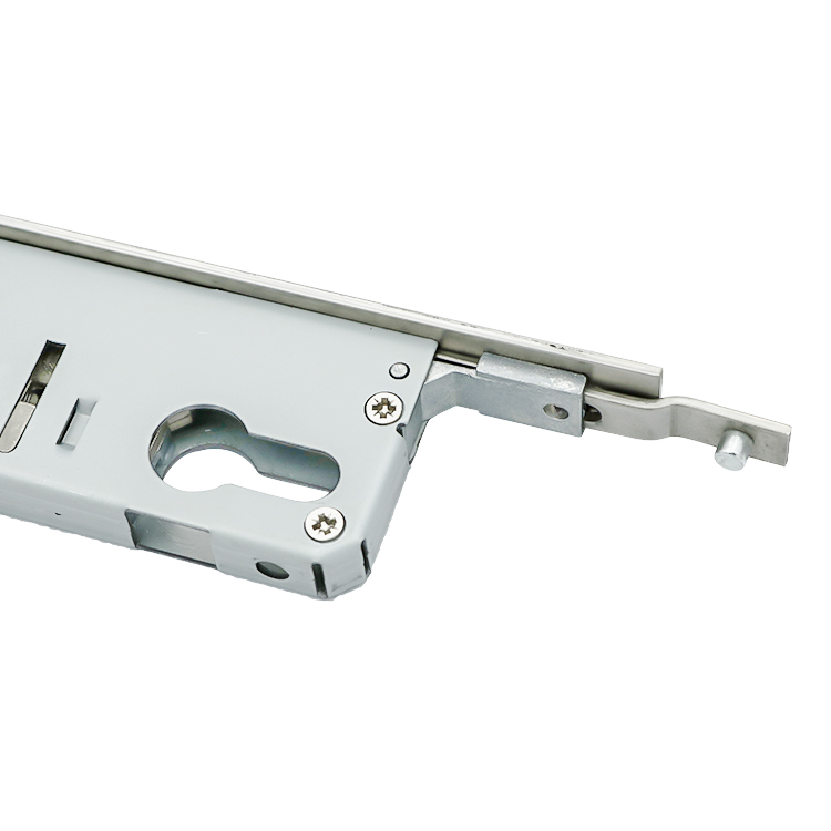
For pin or rod systems, photograph the connectors. Then measure their diameter, extension and attachment method. The dual end-pin multipoint mortise lock is mechanically different from a hook-and-roller strip even when its central gearbox appears similar.
Measure the Gearbox, Not Just the Strip
The gearbox is the transmission unit behind the handle and cylinder. It converts handle or key movement into the travel that operates the locking points.
Record the following:
Gearbox Detail
Measurement or Observation
Case height
Top to bottom of the lockcase
Case depth
Faceplate rear to deepest point
Case thickness
Side-to-side body thickness
Latch position
Centre relative to spindle
Deadbolt position
Centre relative to cylinder
Spindle follower
8 mm, 9 mm, 10 mm or measured size
Cylinder format
Euro profile, oval, round or other
Connection system
Rod, rack, stamped strip, screw joint or clipped linkage
Operation
Lever lift, key wind, automatic, split spindle or panic
Handing
Left, right or reversible
Travel
Direction and distance moved by each connection
A visually similar gearbox can drive the linkage in the opposite direction or through a different travel distance. This is why I do not recommend buying a gearbox from front-view photographs alone.
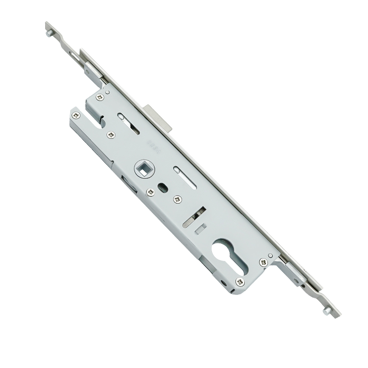
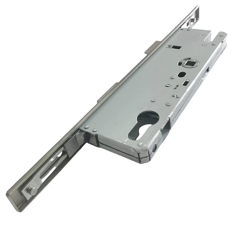
Compare the lock against a clearly documented narrow-faceplate multipoint gearbox and you will see the data that matter: backset, PZ, faceplate dimensions, case depth, handing and upper or lower connection positions.
The Best Way to Identify a Replacement Multipoint Lock
The best way to identify a replacement multipoint lock is to combine measurements, photographs, markings and operating behaviour.
One identifier is weak. A complete record is strong.
Photograph the Entire Mechanism
Take separate photographs of:
The complete faceplate
The gearbox front
The gearbox rear
Each hook, roller or bolt
Top and bottom strip ends
Brand stamps and numbers
The frame keeps
The door profile
The handle and cylinder arrangement
Include a ruler in at least one full-length photograph.
Record Every Marking
Check the faceplate near the latch, gearbox and end sections. Manufacturers may stamp a logo, series name, patent number, production code or backset.
But do not treat a stamp as a complete part number unless the manufacturer confirms it. The same stamped gearbox family may appear in several strip configurations.
Record How the Lock Operates
Write down whether:
The handle must be lifted before locking
The key extends the hooks
The door locks automatically when closed
The outside handle is inactive
The spindle is split
The latch is reversible
A day-latch function is fitted
The lock includes emergency or panic operation
Then test it with the door open.
Slowly.
If the gearbox feels stiff only when the door is closed, the real fault may be door sag, keeper position or excessive seal compression rather than gearbox damage. Replacing the lock without correcting alignment simply transfers the same load into a new mechanism.
uPVC Multipoint Lock Replacement: What Changes With the Door Material?
A uPVC multipoint lock replacement is often treated as a simple hardware swap. That confidence is misplaced.
uPVC doors may contain steel reinforcement, welded corners and routed channels that limit gearbox depth and faceplate width. Composite doors may use different internal reinforcement and edge materials. Aluminium systems often have narrower cavities and highly specific profile interfaces. Timber doors may offer more machining freedom, but careless alterations can weaken the stile.
The lock must match the door.
CHIER’s multipoint door lock range includes long-faceplate, narrow-case, hook, bolt and linked-rod configurations, illustrating why the door material alone cannot identify the required mechanism.
For profile-dependent projects, request a dimensioned drawing through the door and window hardware download centre rather than relying on a generic catalogue image. The site’s document workflow includes model specifications, dimension drawings, mounting information and lock-interface files where available.
Why Accurate Multipoint Lock Measurements Affect Security
This is not paperwork.
The Office for National Statistics reported that police-recorded burglary in England and Wales fell by 9% to 223,456 offences in the year ending March 2026. A falling number is welcome, but 223,456 recorded offences is not an argument for careless door hardware.
The UK government’s Approved Document Q covers standards intended to help doors and windows in new dwellings resist physical attack, including the use of appropriately robust hardware. It applies to new dwellings, not every replacement job, but the engineering principle is plain: security depends on the assembled opening rather than the cylinder or lock strip in isolation.
Secured by Design guidance on locks and associated hardware similarly distinguishes complete door assemblies and replacement security components. PAS 24 is a doorset performance standard. Installing a product that resembles a tested lock does not automatically recreate the tested doorset.
And the UK National Protective Security Authority makes the same point more bluntly: an approved lock fitted to weak or ill-fitting door hardware cannot provide the expected protection. Geometry wins.
A Warning About Fire-Rated Doors
If the multipoint lock is installed in a fire-rated flat entrance door, communal door, escape door or certified doorset, stop before changing the hardware.
The Fire Safety (England) Regulations 2022 guidance emphasises that fire doors must remain suitable for the assessed risk and that responsible persons have inspection duties in covered buildings. My practical interpretation is conservative: verify replacement hardware against the door manufacturer’s evidence and use a competent specialist rather than improvising from dimensions alone.
Seven Measurement Errors That Cause Bad Orders
1. Measuring PZ From Edges
PZ is centre to centre. Edge-to-edge readings depend on the sizes of the holes and are unreliable.
2. Calling Screw Centres “PZ”
Handle fixing centres and PZ are different dimensions. Record both.
3. Ignoring the Frame Keeps
The new lock can fit the door perfectly and still fail because its hooks or rollers do not align with the keeps.
4. Rounding the Backset
A measured 28 mm backset is not a 30 mm backset. Precision does not become optional because the catalogue has fewer filters.
5. Matching Only the Gearbox
Two gearboxes may share the same case outline while using different linkage travel, connection positions or operating direction.
6. Measuring a Bent Strip
Lay the mechanism flat. A twisted faceplate changes overall length and locking-point positions.
7. Ordering Before Diagnosing Alignment
Remove pressure from the lock by testing it with the door open. If it works smoothly open but binds closed, inspect hinges, keeps, seals and frame position before condemning the mechanism.
A Measurement Sheet You Can Send to a Supplier
Copy and complete this specification:
Door material: Door opening direction: Lock manufacturer or marking: Lock operation: Backset: PZ centres: Spindle follower size: Handle fixing centres: Faceplate width: Faceplate length: Faceplate thickness: Faceplate type, flat or U-shaped: Gearbox height: Gearbox depth: Gearbox thickness: Upper locking-point type and distance from spindle: Lower locking-point type and distance from spindle: Hook or bolt projection: Overall strip length: Top connection type: Bottom connection type: Keeper arrangement: Required finish: Photographs attached: Full strip, gearbox front, gearbox rear, lock points, keeps and door profile
For OEM or repeated purchasing, add the drawing revision, door-profile section, expected annual quantity, inspection dimensions and packaging requirements. CHIER’s quality-control and hardware testing process is built around approved drawings, samples and defined inspection points rather than appearance alone.
FAQs
What measurements do I need for a replacement multipoint door lock?
To identify a replacement multipoint door lock, measure the backset, PZ or handle-to-cylinder centres, faceplate width and length, spindle follower size, handle fixing centres, overall strip length, and the distances from the spindle centre to every hook, roller, bolt, or shootbolt connection on the original assembly.
You should also record the gearbox dimensions, door handing, operating method, cylinder format, keeper layout and any manufacturer markings. Photographs of the full strip and both sides of the gearbox reduce identification errors.
What is the backset on a multipoint door lock?
Multipoint door lock backset is the horizontal distance from the front edge of the faceplate to the exact centre of the square spindle follower that receives the handle, and it determines whether the gearbox will sit correctly inside the existing door profile and align with the handle preparation.
Measure at a right angle to the faceplate. Do not measure from the decorative door edge, the gearbox body or the side of the spindle opening.
What does PZ mean on a multipoint lock?
PZ measurement is the centre-to-centre vertical distance between the square handle spindle follower and the centre of the euro-profile cylinder or key opening, and it determines whether the existing handle, escutcheon, cylinder cut-out, and gearbox interface can line up without drilling or forcing the hardware.
PZ is not the distance between the handle fixing screws. Both measurements should appear separately on your replacement specification.
Can I replace only the multipoint lock gearbox?
You can replace only the multipoint lock gearbox when the replacement case has the same backset, PZ, spindle size, faceplate interface, connection points, travel, handing, and operating sequence as the original, while the rods, hooks, rollers, keeps, and full-length strip remain straight, synchronized, and serviceable.
A gearbox-only replacement is a poor repair when the strip is bent, the linkage is worn or the door is forcing the locking points against misaligned keeps.
How do I identify an unbranded multipoint door lock?
The best way to identify an unbranded multipoint door lock is to record every measurable dimension, photograph the entire faceplate and gearbox from both sides, note the hook or roller pattern, check the spindle and cylinder arrangement, and compare the operating sequence rather than trusting appearance or one stamped number.
Send the supplier a completed measurement sheet, full-length photographs, door-profile information and keeper dimensions. An exact geometric match matters more than finding a familiar-looking label.
Your Next Steps
Remove the lock with the door open, measure every interface in millimetres and photograph the mechanism against a steel rule. Do not order from backset and PZ alone.