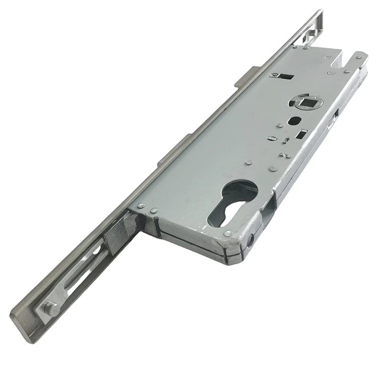
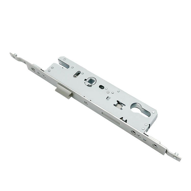
Looking for hardware solutions that meet European / American standards?
Use this guided inquiry modal to move from a generic quote form to a clearer technical conversation. Buyers can choose whether they need pricing, CAD / 3D files, or OEM / ODM support before sharing contact details.
Compatibility-first design across door / window systems
Repeatable production with clear inspection checkpoints
Documentation and change control for long-running programs
Responsive engineering support for fit and field feedback
On a narrow-stile door, a 5 mm specification error can move the handle into the glazing bead, push the lockcase into a thermal barrier, weaken the fixing zone, or make an otherwise respectable multipoint lock impossible to assemble.
So why do buyers still order these locks from photographs?
I will be blunt: the industry talks about multipoint lock backset as though it were one clean number. It is not. The number only becomes useful when we know its reference point, the lockcase depth behind it, the profile cavity around it, and the operating hardware attached to it.
That distinction matters most on narrow aluminium stiles. There is little spare space, little tolerance for bad machining, and nowhere for an oversized gearbox to hide.
What a Multipoint Lock Backset Actually Measures
A multipoint lock backset is the horizontal distance from the lock faceplate or door-edge reference plane to a specified operating centerline inside the lock.
But which centerline?
That depends on the lock architecture and the manufacturer’s drawing.
On many lever-operated multipoint door locks, the backset is measured to the center of the handle follower or spindle. On certain narrow-stile deadlocks, manufacturers instead state a cylinder backset, meaning the distance from the lock face to the cylinder centerline.
ASSA ABLOY defines backset as the distance between the front edge of a mortise lock and the center of the locking cylinder in its door-lock terminology guide. Schlage uses the same basic principle for bored locks but measures from the door edge to the cross-bore centerline in its door hardware glossary.
Both definitions are valid. They describe different lock formats.
My rule is simple: never place a purchase order until the supplier’s drawing identifies the exact backset reference line.
Backset Is Not Case Depth
This is where expensive mistakes begin.
Backset tells you where an operating centerline sits. Case depth tells you how far the physical lock body extends into the door. A 25 mm backset lock may have a case that extends substantially farther than 25 mm.
Thin profiles punish.
If the buying team checks only the stated aluminium door lock backset while ignoring the rear case envelope, mounting bosses, screw heads, rod connections, cylinder cam, thermal break, reinforcement chamber, and glazing pocket, the sample may look correct from outside while being mechanically impossible inside.
What exactly did the backset number prove?
Not much.
Backset, PZ, Faceplate, and Case Depth Compared
Dimension
What It Measures
Why It Matters on a Narrow Stile
Common Buying Error
Backset
Faceplate or door-edge reference to the specified spindle or cylinder centerline
Controls handle position, cylinder position, case location, and clearance from glazing
Assuming it equals total lock depth
Case depth
Faceplate reference to the rear of the lock body
Determines whether the gearbox physically fits inside the extrusion
Requesting a 25 mm backset without requesting the case drawing
PZ or centers
Center of handle spindle to center of cylinder
Determines handle-and-cylinder compatibility
Matching the backset but ordering 85 mm centers for a 92 mm preparation
Faceplate width
Width of the visible strip fitted to the door edge
Must match the groove, fixing surface, and edge preparation
Forcing a wide faceplate onto a slim extrusion
Faceplate thickness
Thickness of the strip at the door edge
Changes flushness, keeper relationship, and closing clearance
Ignoring a 1–2 mm projection at the door edge
Follower size
Square spindle opening, often specified in millimetres
Must match the handle spindle and required torque transfer
Assuming all followers are 8 mm
Locking-point position
Distance from gearbox datum to hooks, rollers, bolts, or mushrooms
Determines whether every point meets its keeper
Ordering by overall strip length alone
Overall strip length
Total faceplate or drive-rail length
Affects cutting, extensions, top clearance, and threshold details
Treating two equal-length strips as interchangeable
The stronger engineering discussion belongs inside the complete lock boxes and gearboxes range, because the lockcase, transmission, follower, drive rail, and fixing pattern decide whether a compact backset becomes a reliable mechanism or a warranty problem.
What Backset Is Needed for a Narrow-Stile Door?
There is no universal narrow-stile backset.
Anyone who gives a single answer without seeing the profile section is guessing.
The correct backset is the smallest validated size that positions the handle and cylinder correctly while leaving enough internal space for the lockcase, rods, fasteners, glazing, reinforcement, drainage, seals, and any thermal barrier.
That is the hard truth.
Real Narrow-Stile Backset Examples
Actual narrow-stile products show how fragmented the market is. Adams Rite’s MS1850S deadlock is offered with these backsets:
Catalog Backset
Metric Equivalent
Practical Interpretation
7/8 inch
22.2 mm
Very compact narrow-stile preparation
31/32 inch
24.6 mm
Inch-derived size close to a nominal 25 mm system
1-1/8 inch
28.6 mm
Compact but with more internal room
1-1/2 inch
38.1 mm
Deeper format for profiles with a larger usable cavity
These are not theoretical conversions. They are published options for the Adams Rite MS1850S narrow-stile deadlock. Its related MS1950P model can work with header and threshold bolts to create a multipoint locking arrangement on narrow-stile aluminium doors.
Metric multipoint door lock families may instead use nominal backsets such as 25 mm, 30 mm, 35 mm, 40 mm, or 45 mm. Wider timber, composite, and steel door locks often move into the 50–70 mm range.
Do not mix the families casually. A 31/32-inch lock is 24.6 mm, not exactly 25 mm. That 0.4 mm difference may be harmless in one machined profile and unacceptable in another, especially where the cylinder, handle plate, or routing jig has almost no adjustment.
A Practical Screening Guide
The table below is a specification screen, not a substitute for a section drawing.
Backset Range
Typical Profile Situation
Advantages
Main Risks
22–25 mm
Ultra-narrow aluminium storefront, sliding, or slim residential profiles
Preserves slim sightlines and may clear shallow cavities
Small gearbox, reduced fixing space, tight handle and cylinder clearance
28–30 mm
Narrow aluminium profiles with slightly more internal depth
Better internal packaging than ultra-compact formats
May still interfere with glazing pockets or reinforcement
35–38 mm
Less aggressive narrow-stile or medium-stile profiles
More room for gearbox parts, springs, cams, and fixings
Handle may sit too far from the edge for the intended trim
40–45 mm
Medium aluminium stiles and some thermally broken systems
Easier mechanism packaging and stronger fixing options
Often too deep for genuinely slim profiles
50 mm and above
Wide-stile, timber, composite, or steel doors
Larger internal mechanism envelope
Usually unsuitable for narrow-stile aluminium sections
My controversial opinion? Buyers often chase the smallest backset for visual reasons when they should be asking whether the profile needs another 5 mm of usable cavity.
A slimmer lock is not automatically a better lock. It may have less room for follower support, spring geometry, cam thickness, fasteners, and rod connections. Compact engineering can be excellent, but compact marketing is cheap.
How to Measure a Multipoint Lock Backset Correctly
A door lock backset measurement should be taken from a controlled reference surface to a clearly identified mechanical centerline.
Do not measure from a rounded extrusion corner. Do not measure from a decorative cover. And do not assume the old handle position is correct merely because somebody managed to install it.
Step 1: Identify the Lock Type
First determine whether the door uses:
A lever-operated multipoint lock
A key-operated deadlock with remote rods
A lift-to-lock system
An automatic multipoint lock
A sliding-door hook system
A panic or emergency-exit configuration
A central gearbox with separate extensions
This tells you whether the relevant backset datum is likely to be the follower, cylinder, keyway, or another manufacturer-defined centerline.
Step 2: Find the Faceplate Reference Plane
Use the flat face of the lock strip or the door-edge plane specified on the drawing.
If the faceplate is still installed, place the end of the measuring tool against the flat faceplate surface. If the lock has been removed, inspect whether the manufacturer’s drawing measures from the faceplate surface, the rear of the faceplate, or the machined door edge.
That tiny distinction matters.
Step 3: Measure Perpendicular to the Operating Centerline
Measure at 90 degrees from the faceplate reference to the center of the handle spindle or cylinder, depending on the lock definition.
Do not follow the curve of a bevelled or radiused door edge. The required measurement is horizontal and perpendicular to the reference plane.
For a lever-operated multipoint lock, remove the handle if necessary and measure to the center of the square spindle opening. For a cylinder-referenced deadlock, measure to the cylinder centerline.
Step 4: Record PZ Separately
PZ, sometimes called lock centers, is normally the vertical distance between the handle spindle center and the cylinder center.
Backset and PZ are separate dimensions.
A replacement lock can have the correct 30 mm backset and still fail because the old preparation uses 92 mm centers while the new gearbox uses 85 mm. The handle holes will not align. The cylinder opening will not align. The trim will expose the mistake.
Step 5: Measure the Full Lockcase Envelope
Record:
Maximum case depth
Case height
Case thickness
Rear projections
Rod or extension couplings
Mounting screw locations
Cylinder projection
Cam sweep
Cable or motor space on electromechanical locks
The best measurement is not the one that confirms the catalog number. It is the one that exposes the obstruction nobody had mentioned.
Step 6: Map Every Locking Point
Measure from a fixed gearbox datum to the center of each hook, roller, mushroom, deadbolt, shoot bolt, or latch.
Then check those dimensions against the frame keepers.
The multipoint lock is a coordinated transmission. One correct central gearbox does not rescue three incorrectly positioned strikes. The article on why multipoint locks must match the correct strike plates explains why keeper geometry and lock travel must be treated as one package.
Step 7: Verify the Door Profile Section
Ask for a dimensional extrusion drawing, preferably in DWG, DXF, STEP, or a clearly scaled PDF.
The profile review should show:
External stile width
Internal clear cavity
Glazing pocket
Glazing bead
Reinforcement
Screw channels
Drainage routes
Gasket grooves
Thermal-break polyamide strips
Faceplate groove
Available fixing substrate
Without that section, “narrow stile” is only a sales description.
The Narrow-Stile Fit Check Most RFQs Miss
A lock fits only when the entire case envelope sits inside the usable cavity and every operating part remains serviceable.
The visible stile width is not the usable stile depth.
A 70 mm external stile may contain a glazing pocket, two aluminium walls, a polyamide thermal break, drainage space, reinforcement, screw bosses, and gasket channels. The remaining lock cavity could be much smaller than the outside measurement suggests.
Use This Go-or-No-Go Test
A narrow-stile multipoint lock should not be approved until all five questions receive a clear “yes.”
Does the full lockcase fit? Compare the maximum rear case depth—not only the backset—with the obstruction map inside the extrusion.
Does the handle clear the door construction? Check the lever sweep, backplate width, cylinder escutcheon, glazing bead, frame stop, and adjacent panel.
Can the lock be fixed into useful material? Screws need controlled engagement. A fastener landing in a thin unsupported wall or empty chamber is not a fixing strategy.
Do all locking points meet their keepers? Confirm vertical centers, hook direction, throw, compression range, and adjustment allowance.
Can the lock be removed later? A lock that requires deglazing the door or destroying trim for routine replacement is a service-design failure.
The correct frame tolerances for preventing hardware binding should also be agreed before production. A perfectly selected backset cannot compensate for a leaf that is twisted, dropped, over-compressed by seals, or closing against misaligned keepers.
Hard Evidence: Backset Alone Is Not a Security Specification
Security brochures love lock counts.
Three hooks. Two rollers. One deadbolt. Shiny arrows everywhere.
But a security claim based on the lock alone is incomplete. The door leaf, frame, keepers, reinforcement, cylinders, fasteners, glazing retention, installation, and operating force determine whether the locking system performs under attack and remains usable afterward.
The UK Treats Security as a Doorset Result
England’s Approved Document Q for security in dwellings covers doors and windows intended to resist physical attack. Its guidance treats robustness and appropriate hardware as properties of the doorset, with tested security performance such as PAS 24 used as the compliance route.
That regulatory position is sensible. A multipoint lock backset is a fit dimension, not a burglary-resistance grade. A 25 mm gearbox in a weak, poorly reinforced stile does not become secure because the brochure says “five-point locking.”
Current Crime Data Makes Weak Specifications Hard to Defend
The UK Home Office’s 2023 Commercial Victimisation Survey estimated that 26% of business premises—around 409,000 locations—experienced at least one covered crime during the preceding 12 months. Burglary, including attempted burglary, affected an estimated 8% of premises.
The earlier 2022 Commercial Victimisation Survey reported that 66% of surveyed premises used security window or door locks as a crime-prevention measure.
Locks matter. But specification quality matters more than lock ownership.
Accessibility Can Overrule a Compact Mechanical Choice
The 2010 ADA Standards for Accessible Design require operable door hardware to be mounted between 34 inches and 48 inches, or 865–1,220 mm, above the finished floor. Operable parts must also be usable with one hand without tight grasping, pinching, or twisting of the wrist.
Why mention ADA in an article about backset?
Because narrow lock geometry affects handle clearance, lever choice, cylinder placement, operating force, and the temptation to use awkward thumbturns or compact trim. A lock can fit the extrusion and still create an unacceptable user interface.
Common Multipoint Door Lock Backset Mistakes
Ordering by Backset and PZ Alone
Backset plus PZ is not a complete lock identity.
You still need the faceplate, spindle, cylinder format, case dimensions, lock direction, latch position, deadbolt throw, hook centers, roller centers, strip length, extensions, fixing pattern, and keeper set.
Two locks can share a 35/92 designation and have almost nothing else in common.
Measuring to the Wrong Centerline
This happens when one supplier means spindle backset and another means cylinder backset.
The numbers can look plausible. The manufactured preparation will not.
Place the reference centerline directly on the drawing and label it. Do not rely on a spreadsheet heading that simply says “BS.”
Treating 25 mm and 24.6 mm as Identical
Sometimes they are functionally interchangeable.
Sometimes they are not.
The difference can alter cylinder centering, trim alignment, machining, or the remaining aluminium around the mortise. Inch-derived narrow-stile hardware must be checked against metric extrusion tooling before anybody approves “equivalent” substitutions.
Ignoring the Rear of the Gearbox
Catalog drawings often make the front half easy to read and the rear projections easy to overlook.
I inspect the cam sweep, spring housings, screw heads, motor casing, sensor connections, rod joints, and any anti-drill plates. The rear-most component controls the real cavity requirement.
Selecting More Locking Points Than the Door Can Hold
More points create more interfaces.
Each interface needs a keeper, fixing substrate, alignment tolerance, and enough frame strength to receive load. A three-point system that engages deeply into reinforced keepers may outperform a five-point system with shallow engagement and poor screw purchase.
The appropriate test discussion is covered in common strength tests for door and window hardware. Ask what was tested, how it was mounted, what load was applied, and whether the complete door assembly or only the loose component passed.
Copying a Timber-Door Specification onto Aluminium
A timber or composite door may provide generous case depth and widespread screw purchase. A narrow aluminium extrusion does not.
The same nominal multipoint door lock backset can behave differently because the material, wall thickness, cavity shape, reinforcement, and keeper attachment have changed. For a better profile-first selection process, use the guide on selecting a multipoint lock for aluminium entrance doors.
What the Best Multipoint Lock for Narrow-Stile Doors Looks Like
The best multipoint lock for narrow-stile doors is not necessarily the smallest model.
It is the system that satisfies six conditions:
The backset positions the handle and cylinder correctly.
The full case fits the internal profile cavity.
The faceplate and fixing pattern match the extrusion.
The locking points align with reinforced, compatible keepers.
The operating force remains acceptable under real seal pressure.
The assembly has an appropriate testing and compliance route.
That sounds obvious.
It is not.
Many sourcing failures begin because the buyer asks, “Do you have a 25 mm multipoint lock?” A competent supplier can answer yes. A serious engineering partner should answer with questions about the profile, cavity, PZ, faceplate, spindle, cylinder, locking-point layout, door height, door mass, usage, corrosion exposure, market, and testing requirements.
For custom programs, the OEM and ODM hardware engineering process is the better starting point because it allows the profile drawing, fit envelope, samples, inspection dimensions, packaging, and revision control to be reviewed before repeat production begins.
FAQs
What is a multipoint lock backset?
A multipoint lock backset is the horizontal distance from the lock faceplate or door-edge reference plane to the operating centerline identified by the manufacturer, usually the handle spindle on a lever-operated multipoint lock or the cylinder centerline on certain narrow-stile deadlocks.
It controls where the gearbox, handle, and cylinder sit inside the door. Backset must not be confused with case depth, PZ centers, faceplate width, or locking-point positions.
How do you measure a multipoint lock backset?
To measure a multipoint lock backset, close the door, identify the flat faceplate reference plane, and measure perpendicular to the center of the handle spindle or other centerline shown on the lock drawing, then confirm PZ, case depth, faceplate width, and locking-point positions separately.
Use a steel rule or caliper where access permits. Remove the handle or cylinder when trim makes the true centerline difficult to identify.
What backset is needed for a narrow-stile door?
The backset needed for a narrow-stile door is the smallest validated size that fits the real internal profile cavity, centers the handle and cylinder safely, clears glazing, reinforcement, drainage, and thermal barriers, and still leaves enough material for reliable fixing and keeper engagement.
Common candidates may include approximately 22–25 mm, 28–30 mm, or 35 mm, but no size should be approved without the lock drawing and extrusion section.
Is a 25 mm backset best for an aluminium door?
A 25 mm aluminium door lock backset is a compact option commonly considered for slim profiles, but it is only suitable when the complete lockcase, faceplate, spindle, cylinder, fasteners, rods, and service clearances fit the extrusion without cutting into reinforcement, drainage, glazing, or the thermal break.
A 30 mm or 35 mm backset may provide better mechanism packaging when the stile has enough usable depth. Smaller is not automatically stronger or more reliable.
Can I replace a multipoint lock using backset alone?
You should not replace a multipoint lock using backset alone because two locks can share the same backset while differing in PZ centers, faceplate width, case depth, spindle size, cylinder format, hook or roller positions, strip length, drive travel, handing, and keeper geometry.
Record the full lock reference, photograph the faceplate markings, measure every operating point, and compare the old and new technical drawings before machining or ordering.
What is the best multipoint lock for narrow-stile doors?
The best multipoint lock for narrow-stile doors is a profile-matched system whose backset, case envelope, locking points, keepers, handle, cylinder, fasteners, corrosion package, operating force, and compliance evidence have been checked together on the actual door section rather than selected from a catalog photo.
For commercial, accessible, security-rated, or high-cycle openings, the complete doorset should be validated against the required market standard and operating conditions.
Send the Profile, Not Just a Backset Number
Before requesting a quotation, prepare the profile section, required backset, PZ centers, faceplate dimensions, handle height, cylinder format, locking-point layout, door size, door mass, opening direction, target market, annual quantity, and required test evidence.
Then ask the supplier for three things:
A dimensioned lock and keeper drawing
A profile-fit review before tooling or machining
A functional sample tested inside the real door section
Do not approve a narrow-stile multipoint lock because the backset sounds right.
Prove the fit.
Send CHIER your aluminium profile drawing and project requirements through the OEM/ODM technical review page to compare the backset, gearbox envelope, locking points, keepers, handle, and cylinder as one complete door system.